
Questions 35 - 39
Contents
Questions 35 - 39#
Q35 Thin Lens#
Two thin lenses, \(f = 10\) cm and \(f = -20\) cm are positioned in air as shown in the diagram. If an object is placed at \(0.25\) m from the first (positive) lens and the lenses are separated by \(0.05\) m, where is the image to be found, and what is its magnification?
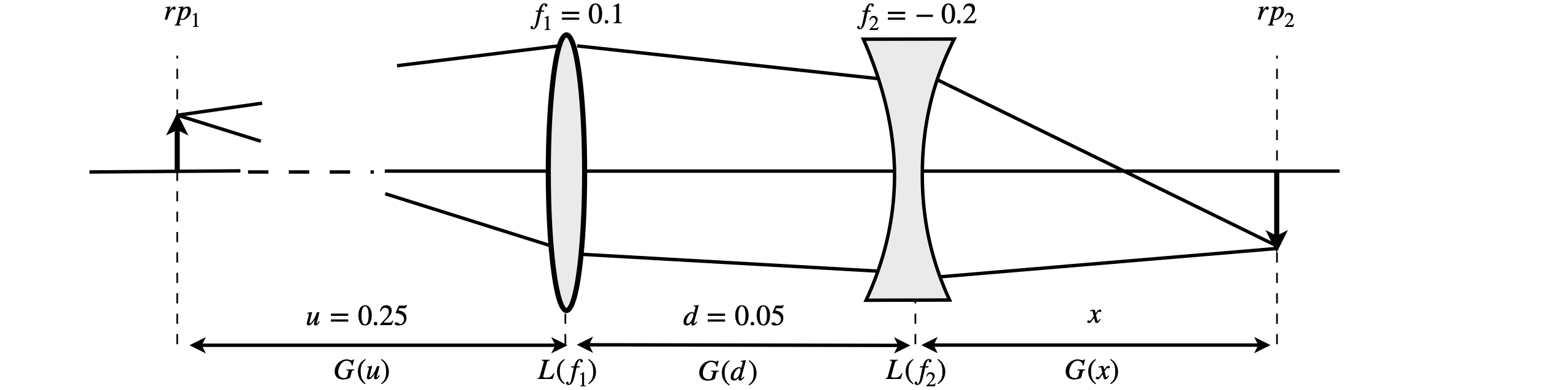
Figure 42. Two thin lenses producing an object-image relationship.
Strategy: Label the known distances as \(u\) and \(d\), and focal lengths as \(f_1\) and \(f_2\), and substitute the numbers into the matrices at the end of the calculation. To find the image distance \(x\) use the object-image relationship of the \(ABCD\) matrix which is \(B = 0\). Take care to write matrices down in the correct order, the reverse of that on the diagram. Use python/Sympy to avoid matrix multiplication errors.
Q36 Thick Lens#
A thick lens is to be used to focus a laser beam. For the best focusing with minimal distortion the most curved surface is presented to the laser. The lens thickness is \(d_L = 6\) mm and it is made of quartz with a refractive index of \(1.48\) at the laser’s wavelength and has surfaces with radii of curvature of \(100\) mm and \(300\) mm. Where is the focal point of the lens if the input beam is effectively parallel?
The lens is shown below with surfaces exaggerated very greatly. Use the matrix in equation 21 for the lens surfaces between the reference planes shown. Use python/Sympy to perform the matrix multiplications.

Figure 43 Geometry of a thick lens.
Strategy: The matrices are set up as before between the reference planes. The radius of the second surface \(r_2\) is made negative because it is concave towards the incoming photons. As the input beam is parallel to the optical axis, make the element \(A = 0\) in the \(ABCD\) matrix to calculate the focal point. The first reference plane is placed at the lens surface, because the input is parallel, i.e. the object distance is at infinity and it would not make sense to have an infinite term in a matrix. Recall that the gap matrices have to have their distances divided by the refractive index. The gap from the lens (\(rp_4\)) to the focal point at reference plane \(5\), (\(rp_5\)) is \(x\).
Q37 Laser profile#
A laser operates at \(600\) nm. Using the values \(L = 0.5\) m, \(f_1 = 0.1\), and \(f_2 = 0.2\) m, calculate the position of the beam waist its value and that of the confocal parameter. Plot a graph of the beam profile between the mirrors making the beam waist at \(z = 0\). The beam waist will need to be multiplied by \(100\) to fit on the same scale as the mirrors.
Q38 Laser cavity matrix#
A laser cavity can contain several mirrors; a common design for a continuously pumped dye laser has three mirrors, a cavity dumped dye laser four; see Figure 44. In such cavities, the sequence of matrices and gaps can become very long. The general equation is
The whole sequence can also be written as \(\displaystyle \pmb{M}=\begin{vmatrix} A & B \\C & D\end{vmatrix}\pmb{M_2}\begin{vmatrix} D & B \\C & A\end{vmatrix}\pmb{M_1}\) where \(\pmb{M_1,2}\) are the matrices foro the end mirrors and \(ABCD\) matrices for the cavity elements between the end mirrors.
Mirror 1 is the output coupler and is where the reference planes are situated. The aim of this question is to show that if \(G_1G_2G_3 \cdots G_n= \begin{vmatrix} A & B \\C & D\end{vmatrix}\) then \(G_n\cdots G_3G_2G_1= \begin{vmatrix} D & B \\C & A\end{vmatrix}\).
(a) Work out the matrix for only the gaps between mirrors, then a gap plus mirror and a mirror plus gap to show that the proposition is true.
(b) In the general case, the result can be found by induction, by first calculating \(\displaystyle G_n\begin{vmatrix} -1 & 0 \\1 & 0\end{vmatrix}G_n\) and then making \(G\) and \(ABCD\) matrix.(This question is based on one in Gerrard & Burch 1975.)
Strategy: In the general calculation you will need to use the fact that from the definition of the matrices for any individual gap or mirror matrix \(A = D = 1\), and also for any individual or product of matrices \(AD-BC=1\)
Q39 Cavity dumped laser#
Show that the equation developed in the previous question applies to the cavity shown in the sketch; Figure 44. The jet of a fluorescent dye in ethylene glycol or a Ti sapphire crystal, is the gain medium, and could be placed at the focus between mirrors 1 and 2 and then the cavity dumper, a crystal with an attached piezoelectric element, is at the focus of mirrors 3 and 4. The cavity dumper crystal has an acoustic field produced in it via an RF source applied to the piezo element and this diffracts, or ‘dumps’, the light out of the cavity. Mirrors \(M_1\) and \(M_2\) have focal lengths \(60\) and \(100\) cm and \(M_3\) and \(M_4\) lengths of \(30\) and \(100\). Gap 1 is \(50\), gap 2 is \(200\) and gap 3 is \(35\) cm. Is this cavity stable? Use python/Sympy to do the calculation. You could also to do repeated calculations based around the values given to look at the stability diagram of this type of cavity.

Figure 44. Diagram of four mirror cavity, showing the configuration for cavity dumping.